Friday, January 9, 2009

Wyliecat width of wishbone on Blueberry

Link to earlier blogs in blog order
Links to earlier blogs in chronological order:
Nonsuch 22 Brochure
Forward looking sonar on Blueberry
MarsKeel stability bulb torpedo on Blueberry
Wyliecat width of wishbone on Blueberry

Some 50 years before Mark Ellis designed the Nonsuch, and Tom Wylie designed the Wyliecat, Sidney Herreshoff was designing small sailboats with wishbone booms, sometimes referred to as "wishboom" rigs. Wishbone boom design has flourished among suppliers of wind surfing equipment.

Tom Wylie's racing oriented boat has a wishbone design considerably wider than the wishbone design of the Mark Ellis Nonsuch cruiser, to allow for some light air sail shape racing advantage. So, "It seemed like a good idea at the time." came into play one more time in my life

The drawing below was based on my "back of the envelope" sketch for the estimator at Accurate Tube Bending in Newark CA. My sketch required a new nose piece and a new tail piece of mild steel bent to fit the original Nonsuch aluminum side tubes. Mild steel was selected for this design instead of the carbon fiber nose and tail pieces that the Wyliecat used with their aluminum side rails. A lot of thought went into electrochemical isolation of the aluminum and steel components.


The tail piece casting is shown below. The side tubes are fitted over the tail piece casting, and held in place with screws drilled through the tube and tapped into the casting. The stainless steel screws have to be coated with some dielectric barrier such as Lanocote to prevent the aluminum, in contact with the steel to "rot" into a crumbly white material.


The new tail piece, shown below along with the old one, is not a casting, but is, instead a bent tubing, the same size as the side tubing, with a pair of ferrules slipped inside these tubes to bridge the joint.


The nose piece casting is shown below. As with the tail piece, the side tubes are fitted over the nose piece casting, and held in place with screws drilled through the tube and tapped into the casting.


The new nose piece, shown bekow along with the old one, is also not a casting, but is, like the tail piece, a bent tubing, the same size as the side tubing, with a pair of ferrules slipped inside these tubes to bridge the joint.


Shown below is the new tail piece fitted, but not yet drilled and tapped for the the joint screws.


Shown below is the new nose piece almost fitted, with one of the ferrules visible on the right hand side.


Shown below is the longer front to back extent of the new tail piece compared to the original tail piece casting.


Shown below is the longer front to back extent of the new nose piece compared to the original casting.


Shown below is a side view of the new nose piece.


Shown below is the new wishbone in place on Blueberry. The original Nonsuch rubber bumpers were retained on the side rails to cushion occasional slamming of the wishbone against the mast when all wishbone control lines happen to be slack.

The length of the original mast to wishbone hangers was retained, though provision was made for an alternative attachment position further forward, as in the Wyliecat design. I was concerned about the length of these hangers until I realized two things:

First, the twin topping lifts could be used to effectively lighten the weight of the wishbone on the leech of the sail in light air conditions.

Second, in all but the lightest air conditions, the front of the wishbone was essentially supported by the choker lines, at least on the Wyliecat, leaving the mast to wishbone support lines slack.

There are wishbone hanger length, hanger position, choker line attachment and wishbone angle design details involved here that are yet to be explored.


The picture below shows the double topping lift of port and starboard lines, running from the mast head towards the rear of the wishbone, similar to a pair of running back stays.

The green, starboard topping lift, and red, port topping lift, are each spliced to a shackle. A shorter length of line is spliced to the shackle and continues on to another splice on a shackle at the mid point of the rear of the wishbone. Those two fixed lengths combine to hold the wishbone safely above the cockpit. The lower fixed length lines each have an adjustable length line beside them, to use as a topping lift for raising the wishbone.

Either side of the topping lift may be used to raise the rear of the wishbone for hoisting the sail, or reefing the sail. After each of these procedures, the topping lift is released, with the leech of the sail supporting the wishbone.

In light air sailing conditions, the windward topping lift can be tensioned to ease leech tension enough to allow a desired amount of twist to the sail. When the windward topping lift is tensioned, this moves the wishbone towards the leeward side, providing slightly more room for the draft curve of the sail inside the wishbone in light air sailing.

When tacking in light air, the leeward topping lift is tensioned to match the position of the windward topping lift, the tack is initiated and the windward topping lift is released, to become the slack, leeward topping lift.

Each topping lift has a two part tackle of blocks at the rear side of the wishbone. The topping lift line then runs through hanger blocks along the side of the wishbone to a second two part tackle of blocks running from the wishbone to the deck and back to the cockpit.

The resultant four part tackle makes the level of effort for topping lift adjustment quite reasonable. This is shown in the choker line picture, below this one.


The two choker control lines start at a pad eye on each side of the mast, pass through blocks on either side of the center of the nose piece, and through blocks at the beginning pad eyes, then down through a single block in front of the mast.


The picture below shows a one piece choker line beginning at each side of the mast, running out to blocks at the nose piece of the wishbone, and around a single block supporting a triple block below it. When the choker line is slack, allowing the wishbone to relax to a fully forward of the mast position, the single block pulls the triple block up as high as it ever gets. Pulling on either the port side or starboard side choker line draws that triple down the front of the mast closer to the double block between the two cheek blocks on the mast near the deck.


Having port and starboard choker lines, port and starboard topping lift lines, and a double ended main sheet, with port and starboard winches, makes single single handed sailing rather convenient.

Well, except for one design detail. The double sided topping lift works wonderfully to adjust the twist in the upper part of the main without interfering with the leeward side of the main. What about hoisting the sail or shaking out a reef or two back to a full sail?

The two lines of the double sided topping lift  come together at the top of the mast in a very narrow V. This makes it almost impossible, in any sort of breeze, to hoist the fully battened sail, with its large roach, in between the topping lift lines. The solution to that is a bungee cord, running from one topping lift line around the mast to to the other line. The two end of the bungee cord are spliced around a thimble to allow the bungee to slide up and down to topping lift line as required. the picture below shows both topping lifts pulled tight enough to hold the wishbone in place with the sail down.


In the picture below, the port topping lift is holding up the wishbone while the starboard topping lift being slack, allows the bungee cord to pull the starboard topping lift back toward the mast allowing the sail to be fully hoisted without snagging the sail on the topping lift.

The strategy is to allow the wishbone to blow off to the leeward side of the boat, for this example to the starboard side. Notice that with the starboard topping lift eased, the bungee cord pulls that starboard topping lift back towards the mast. As the sail is hoisted, the headboard car keeps the top of the sail between the two topping lift lines. With leech of the main flapping in the breeze on the starboard  side,  none of the full battens catch on that pulled forward starboard topping lift.


With the main fully hoisted, ease the port topping lift so both topping lifts are pulled back towards the mast until one or the other topping lifts need to be tensioned to hold up the wishbone when the main is to be dropped.


Thursday, December 18, 2008

MarsKeel Stability Torpedo Bulb on Blueberry

Link to earlier blogs in blog order
Links to earlier blogs in chronological order:
Nonsuch 22 Brochure
Forward looking sonar on Blueberry
MarsKeel stability bulb torpedo on Blueberry
Wyliecat width of wishbone on Blueberry

For Blueberry, light air, flat water sailing is pure bliss. Sailing on San Francisco Bay can provide, on most summer days, conditions ranging from light air and flat water to near gale force winds with waves to match.

For most sail boats, including Blueberry, reaching downwind in heavy swells can be "interesting". Over the years, photographers have documented truly spectacular knock downs, round ups and other results of sudden changes in apparent wind. Such "interesting times" are more a matter of "when" than "if" for those of us interested in racing. To improve the recovery from "when", a Mark Ellis designed, MarsKeel built, 450 lb split bulb torpedo was bolted and faired into the bottom 4 inches of keel so as not to increase draft, but to add stability in case of knock down. Original keel lead was 1800 lb. Total keel lead is now 2250 lbs.

The pictures below document the installation process.

The split bulb, threaded rod, with nuts and washers to fit, arrived on a pallet. Each half bulb weighed 225 lbs. The piece of door skin veneer shown on the pallet was traced from one of the bulbs and used to transfer the positioning location of the torpedo and the bolt holes to the keel.


Bottom paint was ground off the keel to allow room for the keel and fairing epoxy. The door skin template tracing for the keel and the bolt hole positions is shown below. The template was applied to both sides of the keel.


The bolt holes were drilled from each side, to meet in the middle. Small pilot holes were drilled and adjusted to a single, corrected, pilot hole before the holes were very gradually enlarged to fit the threaded rod supplied by MarsKeel. Why so gradually? Drilling through a lead keel is marginal entertainment, with ample opportunities to snap off a suddenly stuck drill bit.


Wrestling each half bulb onto the keel bolts is truly an exercise in heavy lifting. The plank holding the split bulb was lifted, one end at a time, to the level of the template mark. The half keel bulb was then slid on to the keel bolts. Much easier said than done.


With the bulb half loosely in place, before the bolts are tightened, a layer of thickened epoxy is applied to the keel and the keel bulb half. The hole through the keel was lined with thickened epoxy to firmly grip the threaded rod when the epoxy hardened.

The bolt holes through the keel bulb halves were supplied already countersunk to the width of the flat washers and nuts for the threaded rod. The holes for the threaded rod were drilled slightly loose at the thin ends of the bulb to allow for the change in position as the bulb half was pulled into the shape of the keel.

The keel bolts were gradually tightened, a little on each bolt, to avoid bending the thin ends of the bulb halves. The keel bolts were then cut off flush with the keel bulbs.


The countersunk holes, with their threaded rods, washers and nuts were filled in and faired to the shape of the outer surface of the torpedo.


The joint between the keel and the bulb halves was filleted with thickened epoxy.


From the sides the bulb does not look all that massive. From the rear the maximum width make the bulb look more massive than it really is.


The same is true for the view from the front as well.


Since the two forward looking sonar transducers were mounted where one might normally find a pair of transducers, one for speed and one for depth, there was a design question of where to put the usual transducers.

The answer was to use an Airmar triducer, set off to the side of, and about 3 ft behind the keel, to provide NMEA signals for speed depth and temperature.


The bulb was faired with thickened epoxy filler, sanded, and given a rather thick coat of barrier epoxy over all.


As supplied, the bulb was beautifully smooth. Wrestling the halves into place rather marred that finish, hence the fairing compound on both halves.


Next came a layer of epoxy and filler over the halves and the keel section that had been sanded free of coating so the epoxy would stick to the lead of the keel.


More sanding and another barrier coat of epoxy as a preparatory surface for the bottom paint.


Finally the bottom paint over the lot. View from the starboard side.


View from port side.


View from the stern. Just before the travel lift took it away for launching.

Sunday, December 14, 2008

Forward Looking Sonar on Blueberry

Link to earlier blogs in blog order
Links to earlier blogs in chronological order:
Nonsuch 22 Brochure
Forward looking sonar on Blueberry
MarsKeel stability bulb torpedo on Blueberry
Wyliecat width of wishbone on Blueberry

This blog entry is a step by step documentation of the installation of the Interphase-tech forward looking sonar installed on Blueberry.

The function of the two sonar transducers is explained below. The installation procedures are shown below that.


Total installation time was a couple of hours. The trickiest part was measuring the angle of the hull to work out the cut angle of the fairing block. It is MOST IMPORTANT that you proof your calculations and your table saw settings with a "proof of concept" block of wood before you cut the fairing block. You will see why further down in the pictures below.

The two sonar transducers may be either transom mounted of through hull mounted. The trade offs are this: would you prefer ease of cleaning slime from the transom mounted transducers or having the through hull transducers closer to the pitch center of the boat.

I opted to have the two through hull transducers are mounted reasonably close to the pitch center of the boat. In this installation, the most convenient location was in the port and starboard lockers at the aft end of the two bench seats in the cabin.

A rectangular hole is cut through the floor of the locker. This hole needs to be large enough to install the upper half of the fairing block. This is explained next.

The two transducers ride below the hull just far enough to accomplish two things. First, the transducer has to be vertical to the water surface around the boat. The transducer has to be slightly below the hull to avoid most of the small air bubbles traveling along the hull as the boat move through the water.

To accomplish this, the transducer sits on a fairing block. The fairing block is sawn in half on an angle such that angle of the cut matches the angle of the hull at the installation point.

The picture below shows the cut through the port side locker floor. The cut has to be large enough to allow you to not only tighten the fairing block in place but to fillet the bedding material between the fairing block and the inner surface of the hull.

Back filling the area around the installed fairing block with thickened epoxy to pick up a little extra structural strength from the original locker flooring seems like a good idea to me.


This shows the cut through the starboard locker floor.


The picture below shows the hole sawn though the hull for the transducer stem.


The picture below shows the port side black colored transducer, the bronze transducer stem, with the stem and the transducer lead threaded through the outside half of the sawn transducer block.


The picture below shows the starboard side black colored transducer, the bronze transducer stem, with the stem and the transducer lead threaded through the outside half of the sawn transducer block. Notice there are two leads from the starboard transducer, one for the vertical beam transducer, and the other for the starboard 90 degree horizontal sweep beam.


The picture below shows the Sikaflex bedding compound between the transducer and the bearing block.


The picture below shows the Sikaflex bedding compound being applied to the upper surface of the starboard fairing block and the stem of the transducer.

The guy applying the goop is Dan Jones, who runs Marine Technical Services out of shop space in the Grand Marina of Alameda CA. Dan can be reached on his cell phone at 510-913-0022.

Dan has a wood working shop that those passionate about fine woodworking will truly appreciate. He made the calculation and cutting of the fairing blocks to fit the angle of the hull look easy. It was Dan who convinced me that it is MOST IMPORTANT that you proof your calculations and your table saw settings with a "proof of concept" block of wood before you cut the fairing block. Having a high end table saw capable of precision cuts makes the process quick and easy, though I suspect Dan is skillful enough with wood working that he could have made the cuts with a hand saw.


The picture below shows the Sikaflex bedding compound being applied to the lower surface of the upper half of the fairing block inside the hull.


The picture below shows the two transducers as seen from the bow of the boat.


The picture below shows the starboard side transducer and the fat, outer side of the tapered fairing block.


The picture below shows the two transducers from the stern.


The picture below shows the hole behind, and to one side of the keel for an Airmar Triducer for speed, temperature and depth. The hole is offset to one side and about three feet behind the keel to reduce the effects of keel turbulence on the transducer.


The picture below shows the location of the Triducer hole from he starboard side


Friday, December 5, 2008

Nonsuch 22 Brochure

Nonsuch 22 Brochure
Links to earlier blogs in chronological order:
Nonsuch 22 Brochure
Forward looking sonar on Blueberry
MarsKeel stability bulb torpedo on Blueberry
Wyliecat width of wishbone on Blueberry


A brochure is one thing, but actually sailing a Nonsuch® is the real deal. First let me make perfectly clear that Mark Ellis Design Ltd. owns the trademark "Nonsuch" in Canada, the US and the UK. Let me explain that real deal. Many of the major sailing areas around the Great Lakes and the coasts of North America have a Nonsuch specialist who is still the "go to" guy to learn about the Nonsuch.

You can see pictures of many, but by no means all, of the Nonsuch sail boats on the Nonsuch Photo Galleries. You can see the early 1978 history of the owner of the first Nonsuch 30 in the gallery of Gordon Fisher. The gallery of George Hinterhoeller describes the builder of the Nonsuch

Here in the San Francisco Bay area, back in 1979-80 I really wanted a Nonsuch 30. Dave Vickland became a very patient friend in my unrequited love for that boat at that time in my life.

Fast forward 30 years, and Dave Vickland was still available to help me with a more affordable version of my dream Nonsuch 30, by finding me a Nonsuch 22.

Here is the link to his brokerage page at Bay Island Yachts, and some of Dave's text from that page.


These are wonderful sailboats, true single-handers. Take grandma out for the day... she won't get in the way. The Nonsuch is so simple (and fast) that just about nobody believes it until they sail on one. Then, everything changes. Then, they get truly curious... how can this work so well without a jib...? Nonsuch owners know why... come on out and sail, we'll show you why and how.

As owner of three Nonsuches - N22, N30, and N36 - through the past twenty years, we have a Nonsuch expert on our staff. Dave Vickland managed the exclusive San Francisco Bay dealership for Hinterhoeller's Nonsuch in its sales heydays, 1983 through 1990. Dave knows how to sail a Nonsuch, how to sail it well, and just about anything else that is unique to these wonderful and simple boats.
Dave watched me rig my Nonsuch 22 when I took delivery of it in January 2008. His bemused approach to my rigging efforts ("That might work, though you might consider this alternative.") invariably improved my own running rigging design ideas.

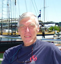
Here is a picture of Dave at the helm of Blueberry the for the first sail in January 2008.


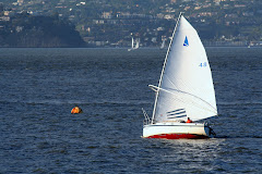
Here is a picture of Dave racing a somewhat smaller catboat on Pinecrest Lake, in 2008.
Sailboat racing is strenuous activity.