Saturday, June 20, 2009

Replacing the mast head sheave

After 18 months of 2 to 3 times a week racing on San Francisco Bay, the main halyard sheave on Blueberry, my Nonsuch 22, sail # 48, gave notice of quitting. A call to Mike Quill Rigging (a specialist in Nonsuch rigging and the source of many Nonsuch replacement parts) outlined for me what I was up against in the replacement of this sheave.

With three races in the next week, I was reluctant to pull the mast. Pulling the mast was estimated to be cheaper than having the same pair of riggers (one operating the crane, the other at the mast head) doing the repair without pulling the mast for work at the ground level. If I could source a replacement sheave, before beginning the surgery (the mast head has to come off to get at the sheave) I might be able (if lucky) to keep my racing schedule intact.

Mike explained that some of the 22's had single sheaves and some had dual sheaves. Mine is a single sheave. Mike would need to know the dimensions of my single sheave to see if he has a sheave that might fit. A classic Catch 22 for my Nonsuch 22

So the call went out: Anyone have the dimensions of the single mast head sheave for a Nonsuch 22? The consensus was that another source of custom stainless steel parts was Murray Cressman. Murray is a jewel of a resource, and he is highly recommended by many as well as by me after this project.

Given the choice of sheaves from various suppliers in various sizes, Murray took his best guess, based on sheaves supplied to other Nonsuch owners, and arranged for a Garhauer sheave to be drop shipped from southern California. With a great looking sheave in hand, then came arranging to get the mast pulled. Wonderful service by Murray and I thank him for that.

In the San Francisco Bay area, only a very small percentage of the boats on the water year round, (even those which are dry sailed) have their masts pulled each year. The quotes from the three nearby yards, to my yacht club, included the cost of two riggers at $90.00 each per hour, and crane charges each time for a total out and back in the next day, of an estimated $600.00 US. Hmmmmm....how about another approach?

Since I am a Green Card Canadian, with the first 30 of my 62 years of boat owning in the annual boat haul out great white north, mast pulling was familiar enough for me to use a couple of family and friends. With their help I was able to use my local yacht club dry sail haul out crane, at lower low tide. We were able to pick up the mast at the balance point, at a crane and salary cost of gratitude to those involved.

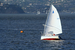
The base of the haul out crane is just above the word Encinal. The tide is much higher at the time of this picture than during the mast haul out.


Same location at Lower Low Water, Large tides ( mast haul out conditions) the next day.


The picture below shows the mast head with the mast head cap removed. The piece of paper taped to the saw horse shows the tidal heights for the day, and a note explaining when the mast would be put back in.


The picture below is a view looking up from the tube of the mast into the mast head cap. The stainless steel pin, through the two flanges of the aluminum casting holds the mast head sheave in place.


The picture below is a view showing one end of the pin in the aluminum casting flange.


The picture below shows the other end of the pin, with a small stainless steel plate welded to the pin and held in place with a flat head screw tapped into the flange. The sheave is resting in the gap between the flanges. So the plan was to remove the old sheave, replace it with the new one, insert the pin, secure the pin in place, and put the cap back into the mast. Easily done eh? Mmmmm....maybe not.....


This shows the elegant Garhauer sheave, the favorite of myself and the choice of Murray Cressman, and a second sheave, sourced locally at the last minute, on the right. And the reason for that would be....shown in the picture below this one......sigh.....


Remember the comment that some Nonsuch masts had single sheaves and others had double sheaves? Well it seems there was some variety in castings as well. My favorite Garhauer could not be fitted even if I had the casting milled out enough to fit into the slot as that would leave the flanges too thin. This was a situation neither Murray nor I had imagined might be the case.


OK, if we are not going to fit the Garhauer, what is Ken Blake doing with the milling machine? Ken Blake runs a small custom metal parts manufacturing company with machine tools ranging in age from the 1940's vintage milling machine being used in the picture to a modern 5 axix CNC machine used for longer runs of small parts production. Ken can be reached at 510-258-3592. Over the years I have used Ken's ability to visualize what has to be done, without a drawing, to create a number of boat related metal parts.


The locally sourced sheave, that would fit betwen the flanges, would not fit far enough into the slot between the flanges because the slot was tapered slightly when cast. The original sheave apparently just barely fit, for a while, but as the bronze bushing wore in use, the sheave tried to drop further into the slot, and in the effort to do so milled, or at least tried to mill a wider slot for itself until it jammed. The jam got my attention, from some 30 feet below the mast head, when pulling up the main sail.


So Ken milled out the slot to the width at the top of the taper, all the way to the bottom of the slot. This allowed us to position the sheave on the stainless steel axis pin, with three thin mylar washers on each side as low friction spacers.


Great, all done now?.....maybe not.... It seems that the stainless pin was not quite square to the stainless plate holding it in between the flanges. Tighten the screw, the sheave jammed....loosen the screw, the sheave spun as it should. OK, some shim stock under one end of the plate, tighten the screw, and all was happy again. Oh yeah, all of the stainless screws threaded into aluminum on this casting were well coated with Forespar Lanocote to prevent electrolytic corrosion in the salt atmosphere.

At the next lower low tide, the spar was picked up just above its balance point, and reinstalled in Blueberry. The next couple of hours were spent re-rigging the wishbone, bending on the sail, and cleaning up the clutter for a beer can race that evening.

After going to all the trouble to source a Garhauer sheave that would fit the size of the line at full hoist of the sail, why was I able to settle for a narrower sheave instead? The high tech halyard had a wonderfully strong mast head shackle spliced into the line. The bury of the splice, tapering from 1/2 inch at the shackle down to the 3/8 inch line beyond the burried tail of the splice, was all on the sheave . So the splice was cut off, the rope end whipped and the dinghy method of fastening the halyard was used.


A loop of the halyard is pushed through the ring in the top of the sail. The short end of the loop tail, with a stopper knot tied in the end, is passed over the top of the sail and pushed down through the loop, the loop is pulled tight. Now only the 3/8 inch line is loading the mast head sheave instead of the fatter spliced section of line. Elegant solution, eh?

Friday, January 9, 2009

Wyliecat width of wishbone on Blueberry

Link to earlier blogs in blog order
Links to earlier blogs in chronological order:
Nonsuch 22 Brochure
Forward looking sonar on Blueberry
MarsKeel stability bulb torpedo on Blueberry
Wyliecat width of wishbone on Blueberry

Some 50 years before Mark Ellis designed the Nonsuch, and Tom Wylie designed the Wyliecat, Sidney Herreshoff was designing small sailboats with wishbone booms, sometimes referred to as "wishboom" rigs. Wishbone boom design has flourished among suppliers of wind surfing equipment.

Tom Wylie's racing oriented boat has a wishbone design considerably wider than the wishbone design of the Mark Ellis Nonsuch cruiser, to allow for some light air sail shape racing advantage. So, "It seemed like a good idea at the time." came into play one more time in my life

The drawing below was based on my "back of the envelope" sketch for the estimator at Accurate Tube Bending in Newark CA. My sketch required a new nose piece and a new tail piece of mild steel bent to fit the original Nonsuch aluminum side tubes. Mild steel was selected for this design instead of the carbon fiber nose and tail pieces that the Wyliecat used with their aluminum side rails. A lot of thought went into electrochemical isolation of the aluminum and steel components.


The tail piece casting is shown below. The side tubes are fitted over the tail piece casting, and held in place with screws drilled through the tube and tapped into the casting. The stainless steel screws have to be coated with some dielectric barrier such as Lanocote to prevent the aluminum, in contact with the steel to "rot" into a crumbly white material.


The new tail piece, shown below along with the old one, is not a casting, but is, instead a bent tubing, the same size as the side tubing, with a pair of ferrules slipped inside these tubes to bridge the joint.


The nose piece casting is shown below. As with the tail piece, the side tubes are fitted over the nose piece casting, and held in place with screws drilled through the tube and tapped into the casting.


The new nose piece, shown bekow along with the old one, is also not a casting, but is, like the tail piece, a bent tubing, the same size as the side tubing, with a pair of ferrules slipped inside these tubes to bridge the joint.


Shown below is the new tail piece fitted, but not yet drilled and tapped for the the joint screws.


Shown below is the new nose piece almost fitted, with one of the ferrules visible on the right hand side.


Shown below is the longer front to back extent of the new tail piece compared to the original tail piece casting.


Shown below is the longer front to back extent of the new nose piece compared to the original casting.


Shown below is a side view of the new nose piece.


Shown below is the new wishbone in place on Blueberry. The original Nonsuch rubber bumpers were retained on the side rails to cushion occasional slamming of the wishbone against the mast when all wishbone control lines happen to be slack.

The length of the original mast to wishbone hangers was retained, though provision was made for an alternative attachment position further forward, as in the Wyliecat design. I was concerned about the length of these hangers until I realized two things:

First, the twin topping lifts could be used to effectively lighten the weight of the wishbone on the leech of the sail in light air conditions.

Second, in all but the lightest air conditions, the front of the wishbone was essentially supported by the choker lines, at least on the Wyliecat, leaving the mast to wishbone support lines slack.

There are wishbone hanger length, hanger position, choker line attachment and wishbone angle design details involved here that are yet to be explored.


The picture below shows the double topping lift of port and starboard lines, running from the mast head towards the rear of the wishbone, similar to a pair of running back stays.

The green, starboard topping lift, and red, port topping lift, are each spliced to a shackle. A shorter length of line is spliced to the shackle and continues on to another splice on a shackle at the mid point of the rear of the wishbone. Those two fixed lengths combine to hold the wishbone safely above the cockpit. The lower fixed length lines each have an adjustable length line beside them, to use as a topping lift for raising the wishbone.

Either side of the topping lift may be used to raise the rear of the wishbone for hoisting the sail, or reefing the sail. After each of these procedures, the topping lift is released, with the leech of the sail supporting the wishbone.

In light air sailing conditions, the windward topping lift can be tensioned to ease leech tension enough to allow a desired amount of twist to the sail. When the windward topping lift is tensioned, this moves the wishbone towards the leeward side, providing slightly more room for the draft curve of the sail inside the wishbone in light air sailing.

When tacking in light air, the leeward topping lift is tensioned to match the position of the windward topping lift, the tack is initiated and the windward topping lift is released, to become the slack, leeward topping lift.

Each topping lift has a two part tackle of blocks at the rear side of the wishbone. The topping lift line then runs through hanger blocks along the side of the wishbone to a second two part tackle of blocks running from the wishbone to the deck and back to the cockpit.

The resultant four part tackle makes the level of effort for topping lift adjustment quite reasonable. This is shown in the choker line picture, below this one.


The two choker control lines start at a pad eye on each side of the mast, pass through blocks on either side of the center of the nose piece, and through blocks at the beginning pad eyes, then down through a single block in front of the mast.


The picture below shows a one piece choker line beginning at each side of the mast, running out to blocks at the nose piece of the wishbone, and around a single block supporting a triple block below it. When the choker line is slack, allowing the wishbone to relax to a fully forward of the mast position, the single block pulls the triple block up as high as it ever gets. Pulling on either the port side or starboard side choker line draws that triple down the front of the mast closer to the double block between the two cheek blocks on the mast near the deck.


Having port and starboard choker lines, port and starboard topping lift lines, and a double ended main sheet, with port and starboard winches, makes single single handed sailing rather convenient.

Well, except for one design detail. The double sided topping lift works wonderfully to adjust the twist in the upper part of the main without interfering with the leeward side of the main. What about hoisting the sail or shaking out a reef or two back to a full sail?

The two lines of the double sided topping lift  come together at the top of the mast in a very narrow V. This makes it almost impossible, in any sort of breeze, to hoist the fully battened sail, with its large roach, in between the topping lift lines. The solution to that is a bungee cord, running from one topping lift line around the mast to to the other line. The two end of the bungee cord are spliced around a thimble to allow the bungee to slide up and down to topping lift line as required. the picture below shows both topping lifts pulled tight enough to hold the wishbone in place with the sail down.


In the picture below, the port topping lift is holding up the wishbone while the starboard topping lift being slack, allows the bungee cord to pull the starboard topping lift back toward the mast allowing the sail to be fully hoisted without snagging the sail on the topping lift.

The strategy is to allow the wishbone to blow off to the leeward side of the boat, for this example to the starboard side. Notice that with the starboard topping lift eased, the bungee cord pulls that starboard topping lift back towards the mast. As the sail is hoisted, the headboard car keeps the top of the sail between the two topping lift lines. With leech of the main flapping in the breeze on the starboard  side,  none of the full battens catch on that pulled forward starboard topping lift.


With the main fully hoisted, ease the port topping lift so both topping lifts are pulled back towards the mast until one or the other topping lifts need to be tensioned to hold up the wishbone when the main is to be dropped.