Links to earlier blogs in chronological order:
Nonsuch 22 Brochure
Forward looking sonar on Blueberry
MarsKeel stability bulb torpedo on Blueberry
Wyliecat width of wishbone on Blueberry
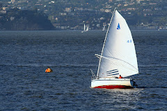
For Blueberry, light air, flat water sailing is pure bliss. Sailing on San Francisco Bay can provide, on most summer days, conditions ranging from light air and flat water to near gale force winds with waves to match.
For most sail boats, including Blueberry, reaching downwind in heavy swells can be "interesting". Over the years, photographers have documented truly spectacular knock downs, round ups and other results of sudden changes in apparent wind. Such "interesting times" are more a matter of "when" than "if" for those of us interested in racing. To improve the recovery from "when", a Mark Ellis designed, MarsKeel built, 450 lb split bulb torpedo was bolted and faired into the bottom 4 inches of keel so as not to increase draft, but to add stability in case of knock down. Original keel lead was 1800 lb. Total keel lead is now 2250 lbs.
The pictures below document the installation process.
The split bulb, threaded rod, with nuts and washers to fit, arrived on a pallet. Each half bulb weighed 225 lbs. The piece of door skin veneer shown on the pallet was traced from one of the bulbs and used to transfer the positioning location of the torpedo and the bolt holes to the keel.

Bottom paint was ground off the keel to allow room for the keel and fairing epoxy. The door skin template tracing for the keel and the bolt hole positions is shown below. The template was applied to both sides of the keel.

The bolt holes were drilled from each side, to meet in the middle. Small pilot holes were drilled and adjusted to a single, corrected, pilot hole before the holes were very gradually enlarged to fit the threaded rod supplied by MarsKeel. Why so gradually? Drilling through a lead keel is marginal entertainment, with ample opportunities to snap off a suddenly stuck drill bit.

Wrestling each half bulb onto the keel bolts is truly an exercise in heavy lifting. The plank holding the split bulb was lifted, one end at a time, to the level of the template mark. The half keel bulb was then slid on to the keel bolts. Much easier said than done.

With the bulb half loosely in place, before the bolts are tightened, a layer of thickened epoxy is applied to the keel and the keel bulb half. The hole through the keel was lined with thickened epoxy to firmly grip the threaded rod when the epoxy hardened.
The bolt holes through the keel bulb halves were supplied already countersunk to the width of the flat washers and nuts for the threaded rod. The holes for the threaded rod were drilled slightly loose at the thin ends of the bulb to allow for the change in position as the bulb half was pulled into the shape of the keel.
The keel bolts were gradually tightened, a little on each bolt, to avoid bending the thin ends of the bulb halves. The keel bolts were then cut off flush with the keel bulbs.

The countersunk holes, with their threaded rods, washers and nuts were filled in and faired to the shape of the outer surface of the torpedo.

The joint between the keel and the bulb halves was filleted with thickened epoxy.

From the sides the bulb does not look all that massive. From the rear the maximum width make the bulb look more massive than it really is.

The same is true for the view from the front as well.

Since the two forward looking sonar transducers were mounted where one might normally find a pair of transducers, one for speed and one for depth, there was a design question of where to put the usual transducers.
The answer was to use an Airmar triducer, set off to the side of, and about 3 ft behind the keel, to provide NMEA signals for speed depth and temperature.

The bulb was faired with thickened epoxy filler, sanded, and given a rather thick coat of barrier epoxy over all.

As supplied, the bulb was beautifully smooth. Wrestling the halves into place rather marred that finish, hence the fairing compound on both halves.

Next came a layer of epoxy and filler over the halves and the keel section that had been sanded free of coating so the epoxy would stick to the lead of the keel.

More sanding and another barrier coat of epoxy as a preparatory surface for the bottom paint.


Finally the bottom paint over the lot. View from the starboard side.

View from port side.

View from the stern. Just before the travel lift took it away for launching.


